
0
Owner's of the AMX TV Converter Box AXB-REL8 gave it a score of 0 out of 5. Here's how the scores stacked up:


Connection and Wiring
3
AXB-REL8 Axcess Relay Controller
Connection and Wiring
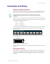
Setting the DEVICE Dip Switch
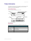
The eight-position Device DIP switch is located on the front panel of the AXB-REL8 as shown in
FIG. 1 on page 1. Each device in the AXlink bus must have a unique AXlink device number.
The device can be 1 of the 255 devices in an Axcess, AXCENT, AXCENT
2
, or AXCENT
3
system.
The device number must match the device assignment in the Axcess program. AMX assigns device
numbers into the following three segments:
! Cards 1 through 95
! Boxes 96 through 127
! Panels 128 through 255
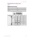
Set the device number by setting the DEVICE DIP switch. The device number is the total of all of
the switches in the ON (down) position. The following table shows the switch numbers and their
corresponding values.
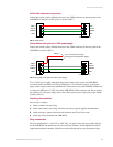
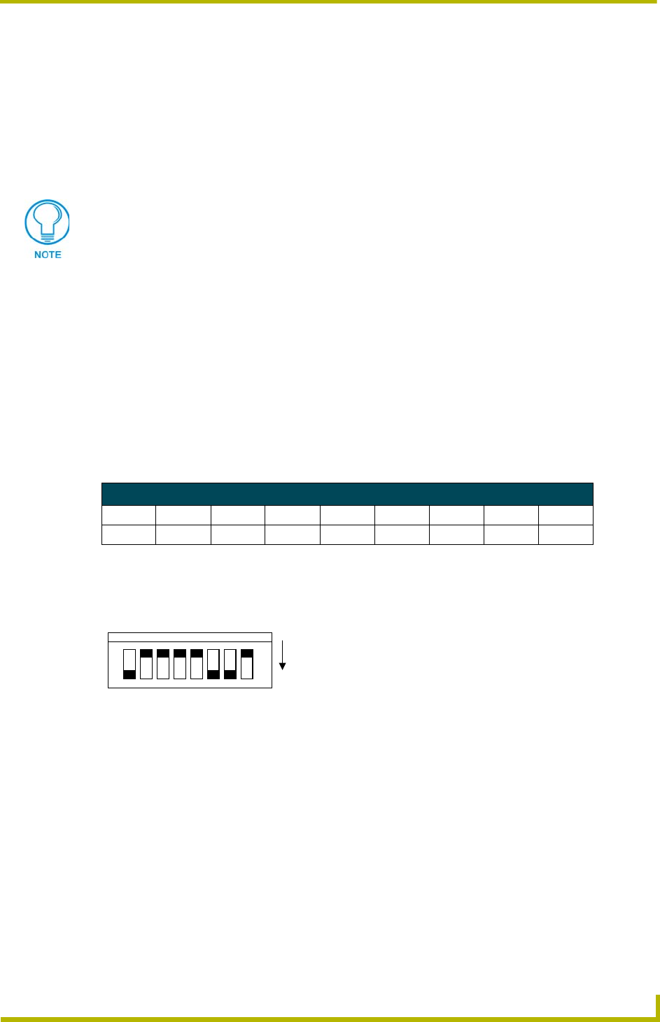
As an example, the following DIP switch (FIG. 2) defines the AXB-REL8 as device number
97 (1 + 32 + 64 = 97).
Set the AXB-REL8 device number before connecting AXlink wiring. Do not install relay wiring at
this time.
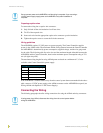
Wiring Requirements
The AXB-REL8 uses a four-pin AXlink Central Controller connector for power and data. If the
distance between the AXB-REL8 and the Central Controller exceeds power consumption limits,
you must connect an optional 12 VDC power supply. Refer to the following section for more
information.
If you later change the device number, remove and reconnect the AXlink connector.
This enters the new device number into memory. The device number takes effect only
on power-up.
Device DIP switch settings
Position12345678
Value1248163264128
FIG. 2 Example device DIP switch with value of 97
ON
DEVICE
1 2 3 4 5 6 7 8


Find Your Products By Category
- Computer Equipment
- Portable Media
- Photography
- Car Audio and Video
- TV and Video
- Household Appliance
- Automotive
- Communications
- Kitchen Appliance
- Laundry Appliance
- Home Audio
- Lawn and Garden
- Power Tools
- Musical Instruments & Equipment
- Baby
- Personal Care
- Video Game
- Marine Equipment
- Fitness & Sports
- Outdoor Cooking
- Cell Phone
Please Login
