

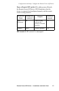
3.4
Owner's of the APC Remote Starter REMOTE POWER-OFF DEVICE gave it a score of 3.4 out of 5. Here's how the scores stacked up:

Remote Power-Off Device — Installation and Quick Start 17
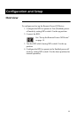
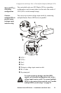
Configuration and Setup: Set up the Remote Power-Off Device
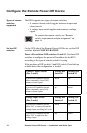
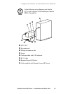
Connect the
switch cable to
the keystone
jack
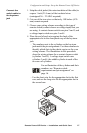
1. Strip the cable jacket (the outer insulation of the cable) to
expose 1 inch (25.4 mm) of the insulated wires
(unstripped 26 – 22 AWG required).
2. Cut one of the two wires so that only .188 inches (4.76
mm) remain exposed.
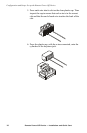
3. Choose your wiring scheme according to the type of
remote switch (contact closure or voltage input) that you
are using. A contact closure switch uses pins 2 and 5, and
a voltage input switch uses pins 3 and 4.
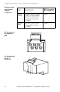
4. Place the end of each wire against the back of the
appropriate slot in the clear plastic cap of the keystone
jack.
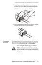
– The numbers next to the cylinders on the keystone
jack match the pin assignments. Use these numbers to
identify which slots in the plastic cap to use for your
wiring scheme. The illustrations in this procedure
show the wiring scheme for a contact closure switch
(cylinders 2 and 5). A voltage input switch uses
cylinders 3 and 4, the middle cylinder in each of the
two rows of cylinders.
– Use the short wire for the appropriate slot in the first
row, and use the long wire for the appropriate slot in
the second row.
For an illustration of the cylinders and their
numbers, see “Remote switch:
requirements and pin assignment” on
page 16.


Find Your Products By Category
- Computer Equipment
- Portable Media
- Photography
- Car Audio and Video
- TV and Video
- Household Appliance
- Automotive
- Communications
- Kitchen Appliance
- Laundry Appliance
- Home Audio
- Lawn and Garden
- Power Tools
- Musical Instruments & Equipment
- Baby
- Personal Care
- Video Game
- Marine Equipment
- Fitness & Sports
- Outdoor Cooking
- Cell Phone
Please Login
