
0
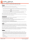
Owner's of the Atlona Marine Radio Atlona HDBaseT Wall Plate Receiver w/RS-232, IR, and Ethernet gave it a score of 0 out of 5. Here's how the scores stacked up:
7
atlona.com
Toll free: 1-877-536-3976
Local: 1-408-962-0515
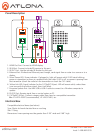
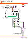
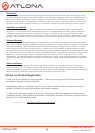
Captive Screw
Connecting
Captive screw connectors are an added feature on the HDWP-RSNET. The Captive screw connectors
allow you to cut cables down to a suitable length, reducing cable clutter while providing a more reliable
connection.
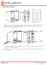
The captive screw connectors have a contact bar that is adjusted to compress the wire against the top
contact plate. Use the screws at the top of the connector to compress the wire against the contact plate.
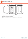
When connecting the cables to the female captive screw connector it is important that the wires be
terminated correctly. The female captive screw connector (see picture A) has a contact plate at the top and
must have the wires touching it for signal to pass. When wired correctly (see picture B) the signal will pass,
incorrectly (see picture C) no signal will pass.
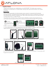
For your convenience the cables do not come pre-terminated. Each item, whether it’s an IR receiver (picture
1), or IR emitter (picture 2), will have exposed wires. Each wire is encased in a different colored cover. Female
captive screw connectors are included: IR (see picture 3) and RS-232 (see picture 4).
IR pin outs have been included for the included IR emitter and IR receiver (see picture 5 & 6). The wires are
colored for each pin (see picture 7 and 8).
White: - Red: +
Red: PWR White: IR Black: ╧
2
1
IR
Clockwise
Counter
Clockwise
Turn the screws clockwise to
raise the contact bar to the upper
contact plate and hold the wires
in place.
Turn the screws counter clockwise
to lower the contact bar to release
the wires.
3
5
6
7
8
A
B
C
- +
Emitter
PWR
IR
╧
Receiver
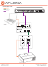
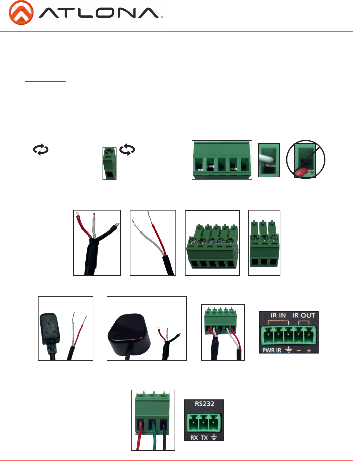
RS-232 pin out will be determined by the RS-232 cable and will connect as Rx (receiver), Tx (transmitter), and
╧ (ground). (See picture 9)
Pin out color will differ per RS-232 cable.
RS-232
4
9


Find Your Products By Category
- Computer Equipment
- Portable Media
- Photography
- Car Audio and Video
- TV and Video
- Household Appliance
- Automotive
- Communications
- Kitchen Appliance
- Laundry Appliance
- Home Audio
- Lawn and Garden
- Power Tools
- Musical Instruments & Equipment
- Baby
- Personal Care
- Video Game
- Marine Equipment
- Fitness & Sports
- Outdoor Cooking
- Cell Phone
Please Login
