
0
Owner's of the Axis Communications Security Camera 25734 gave it a score of 0 out of 5. Here's how the scores stacked up:
- 12 -
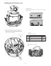
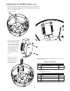
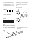
Chart A Wiring Color Code
Power and Control Inputs
(Outside of housing)
CONTROL
RJ45 Ethernet Connector
Separate Power Supplies for Camera and Accessory Power
Camera: 25 watts (VA), 24 VAC, Class 2 Only
Accessory: 27 wattts (VA), 24 VAC, Class 2 Only
POWER
1 Camera Power (24 VAC) Red
2 Camera Power (24 VAC) Orange
3 Accessory Power (24 VAC) Yellow
4 Accessory Power (24 VAC) Green
ALARMS
1 Alarm 1 Blue
2 Alarm 2 Violet
3 Alarm 3 Gray
4 Common White
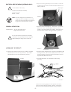
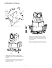
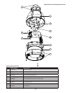
Set screws
Figure 4
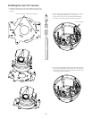
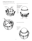
INSTALLING THE HOUSING ASSEMBLY:
1. This unit includes a 1½" NPT housing for a standard 1½"
NPT pipe. The housing can be used with other brackets
designed with 1½" male pipe threads, such as the UNI-WMB1
wall mount brackets.
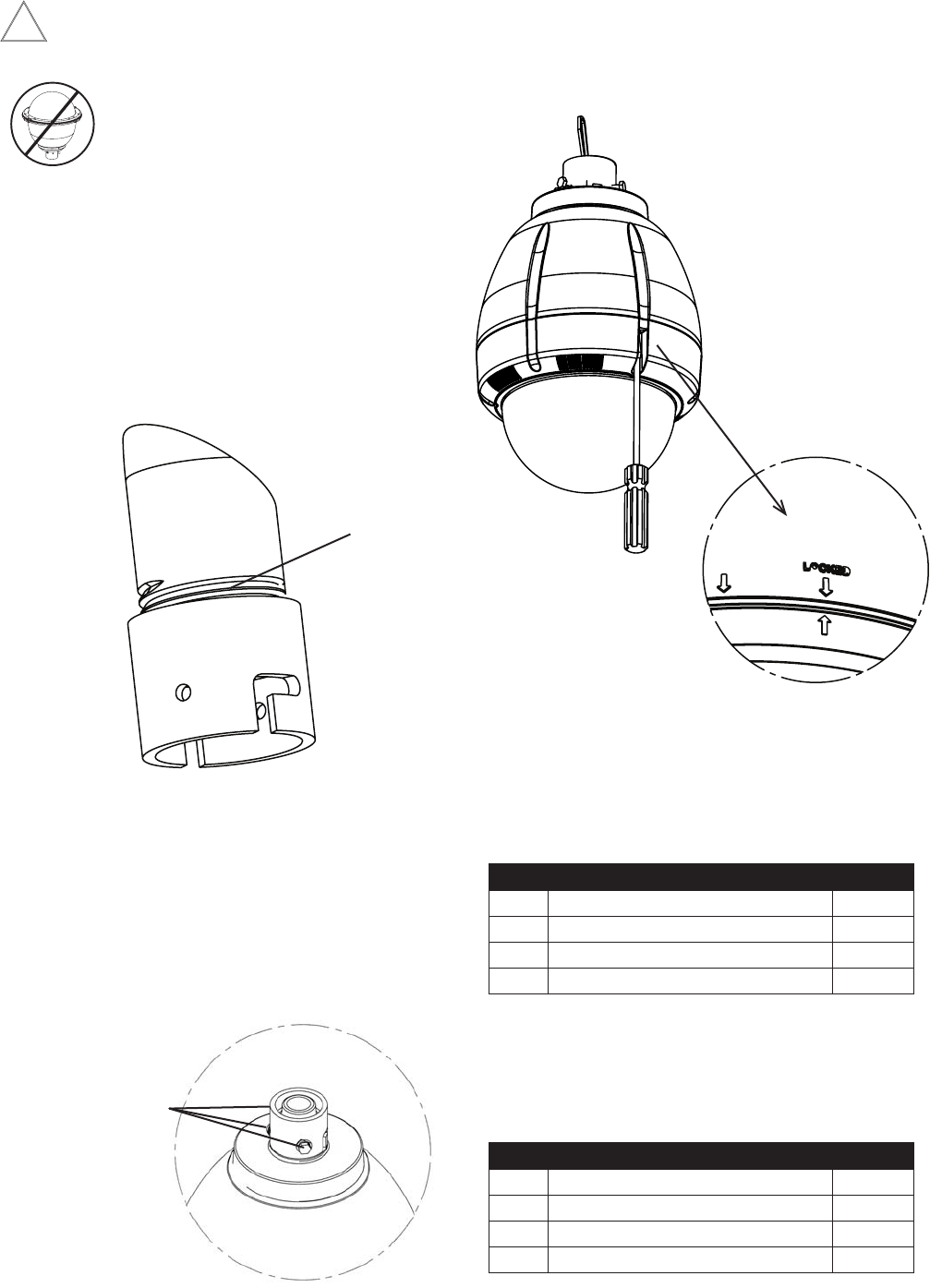
2. Attach the housing coupling (Figure 3).
NOTE: Pipe threads should be clean and rust free.
Use the Teon
™
tape included with
the housing on the threads.
Figure 3
Add thread
sealing tape
NOTE: This unit is designed for operation in an
upright position. Installing the product upside
down may cause damage to the internal
equipment, and will void the warranty.
Be sure the bracket is properly and securely
mounted to a supporting structure capable of rigidly
holding the weight of the entire unit.
!
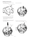
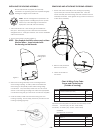
3. Mount the housing assembly to the mounting bracket
and housing coupling. A safety cable is included with
the housing to temporarily hold it while making wiring
connections. Loop the safety cable over one of the set
screws on the housing coupling and make the appropriate
connections using the (2) screw-down connectors supplied.
2. Undo the safety cable and twist the housing onto the
housing coupling. Secure all (3) setscrews provided on the
housing coupling (Figure 4).
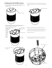
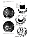
REMOVING AND ATTACHING THE DOME ASSEMBLY:
1. Attach the dome assembly to the housing top by lining
up the three pins with the three keyhole slots. Insert the
dome assembly into the housing and then rotate the dome
assembly clockwise. Then tighten the (3) screws on the front
of the dome assembly.
2. Remove the protective
lm from the dome.
3. Clean the outside of
the dome.


Find Your Products By Category
- Computer Equipment
- Portable Media
- Photography
- Car Audio and Video
- TV and Video
- Household Appliance
- Automotive
- Communications
- Kitchen Appliance
- Laundry Appliance
- Home Audio
- Lawn and Garden
- Power Tools
- Musical Instruments & Equipment
- Baby
- Personal Care
- Video Game
- Marine Equipment
- Fitness & Sports
- Outdoor Cooking
- Cell Phone
Please Login
