
0
Owner's of the Axis Communications Security Camera 25734 gave it a score of 0 out of 5. Here's how the scores stacked up:
- 13 -
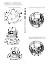
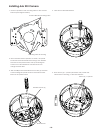
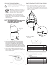
The unit is setup with (2) individual power inputs.
1. Accessory Power (yellow and green wire)
2. Camera Power (red and orange)
If you wish to provide a single power transformer it is recommended that:
1. Be certain that you know the total power consumption of the
housing Heaters (25 watts) + Blowers (2 watts) + camera/pan-tilt
(not supplied)
2. Check the supplied wiring chart to be sure that you have the
proper gauge wire for the distance that you intend to run your
power wires.
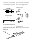
3. Bring power to the 3 and 4 position of the power connector (yellow
and green wire)
4. Two jumpers are provided in the housing packet. Jumper from
the 1
st
position to the 3
rd
position and from the 2
nd
position to the
4
th
position of the terminal block. Be careful not to short between
the yellow and green wires.
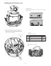
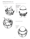
Add 2
jumpers for
single power
input
One Power Supply for both Camera and Accessory Power
52 watts (VA), 24 VAC, Class 2 Only
NOTE: In this combination, run power to the camera connector,
then run jumper wires (not provided) to the accessory
side of the connector.
22
90
20 18
130
16
225
14
350
12
525
10
830
Maximum distance from transformer to housing
Total vA consumed
Wire Gauge
24VACWiring Distances
The following are the recommended maximum distances for 24VAC with a
10% voltage drop. (10% is generally the maximum allowable voltage drop
for AC-powered devices.)
6530
56
90 143 228 362 576
3550
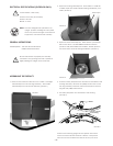
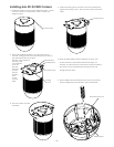
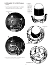
POWER WIRING
Two plug-in wall transformers are included with the housing.
Use one to provide power for the heater and blower in the
housing, and the other for the camera. Determine where
the transformers will be located, then run two sets of power
wires into the wall mount bracket (Four total power wires).
Use the chart below to determine the correct gauge of wire
needed based on the length of the run and the 30vA power
line.
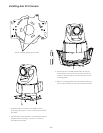
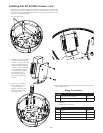
CONNECTING THE TRANSFORMERS (Figure 2)
Determine which transformer will be attached to the camera.
Attach the red and orange wires to the terminal points on the
transformer .
For the transformer which will be used for the heater and
blower, attach the yellow and green wires to the terminal
points.
NOTE: You may attach wires to either terminal, however MAKE
SURE THAT THE TRANSFORMERS ARE ATTACHED TO THE PROPER
CONNECTION ON THE HOUSING.
Green
Yellow
Orange
Red
Camera
Power
Accessory
Power
Camera
Power
Accessory
Power
213 = 24 watts @ 13Vdc
214 = 14 watts @ 12Vdc
231D/232D = 25 watts @ 24Vdc


Find Your Products By Category
- Computer Equipment
- Portable Media
- Photography
- Car Audio and Video
- TV and Video
- Household Appliance
- Automotive
- Communications
- Kitchen Appliance
- Laundry Appliance
- Home Audio
- Lawn and Garden
- Power Tools
- Musical Instruments & Equipment
- Baby
- Personal Care
- Video Game
- Marine Equipment
- Fitness & Sports
- Outdoor Cooking
- Cell Phone
Please Login
