
0
Owner's of the Axis Communications Security Camera 463001 gave it a score of 0 out of 5. Here's how the scores stacked up:
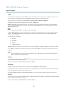

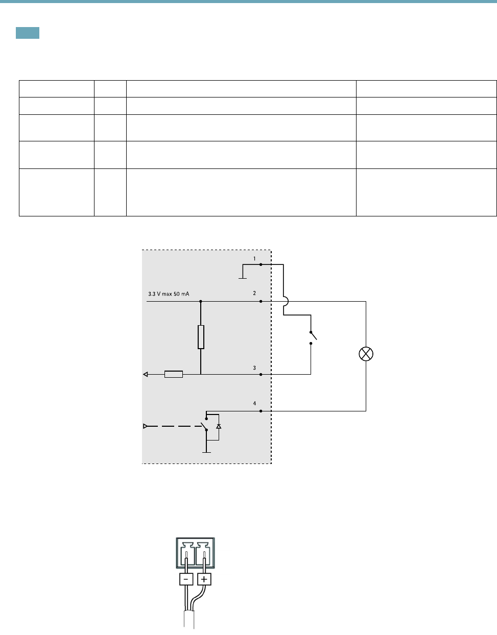
AXIS Q1604-E Network Camera
Technical Specications
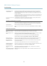
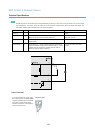
Note
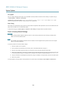
The I/O connector is connected to the housing (fan/heater) on delivery. In the case of a fan or heater error, an input signal
will be triggered in the camera. Set up an action rule in the camera to congure which action the signal shall trigger. For
information about events and action rules, see Events, on page 37.
Function Pin Notes
Specications
0 V DC (-)
1
0 V DC
DC output
2
Can be used to power auxiliary equipment.
Note: This pin can only be used as power out.
3.3 V DC
Max load = 50 mA
Digital Input
3
Connect to pin 1 to activate, or leave oating (unconnected)
to deactivate
0 to max 40 V DC
Digital Output
4
Connected to pin 1 when activated, oating (unconnected)
when deactivated. If used with an inductive load, e.g. a relay,
a diode must be connected in parallel with the load, for
protection against voltage transients.
0 to max 40 V DC, open drain,
100 mA
3.3 V max 50 mA
1
2
3
4
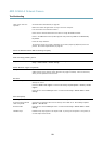
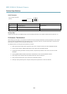
Power Connector
2-pin terminal block for power input.
Use a Safety Extra Low Voltage (SELV)
compliant limited power source (LPS)
with either a rated output power
limited to ≤100 W or a rated output
current limited to ≤5 A.
DC power input
63


Find Your Products By Category
- Computer Equipment
- Portable Media
- Photography
- Car Audio and Video
- TV and Video
- Household Appliance
- Automotive
- Communications
- Kitchen Appliance
- Laundry Appliance
- Home Audio
- Lawn and Garden
- Power Tools
- Musical Instruments & Equipment
- Baby
- Personal Care
- Video Game
- Marine Equipment
- Fitness & Sports
- Outdoor Cooking
- Cell Phone
Please Login
