
0
Owner's of the Crestron electronic Marine Sanitation System QUICK MEDIA DISTRIBUTION CENTER gave it a score of 0 out of 5. Here's how the scores stacked up:

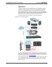
QuickMedia Distribution System Crestron QM-MD4x2
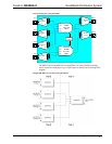
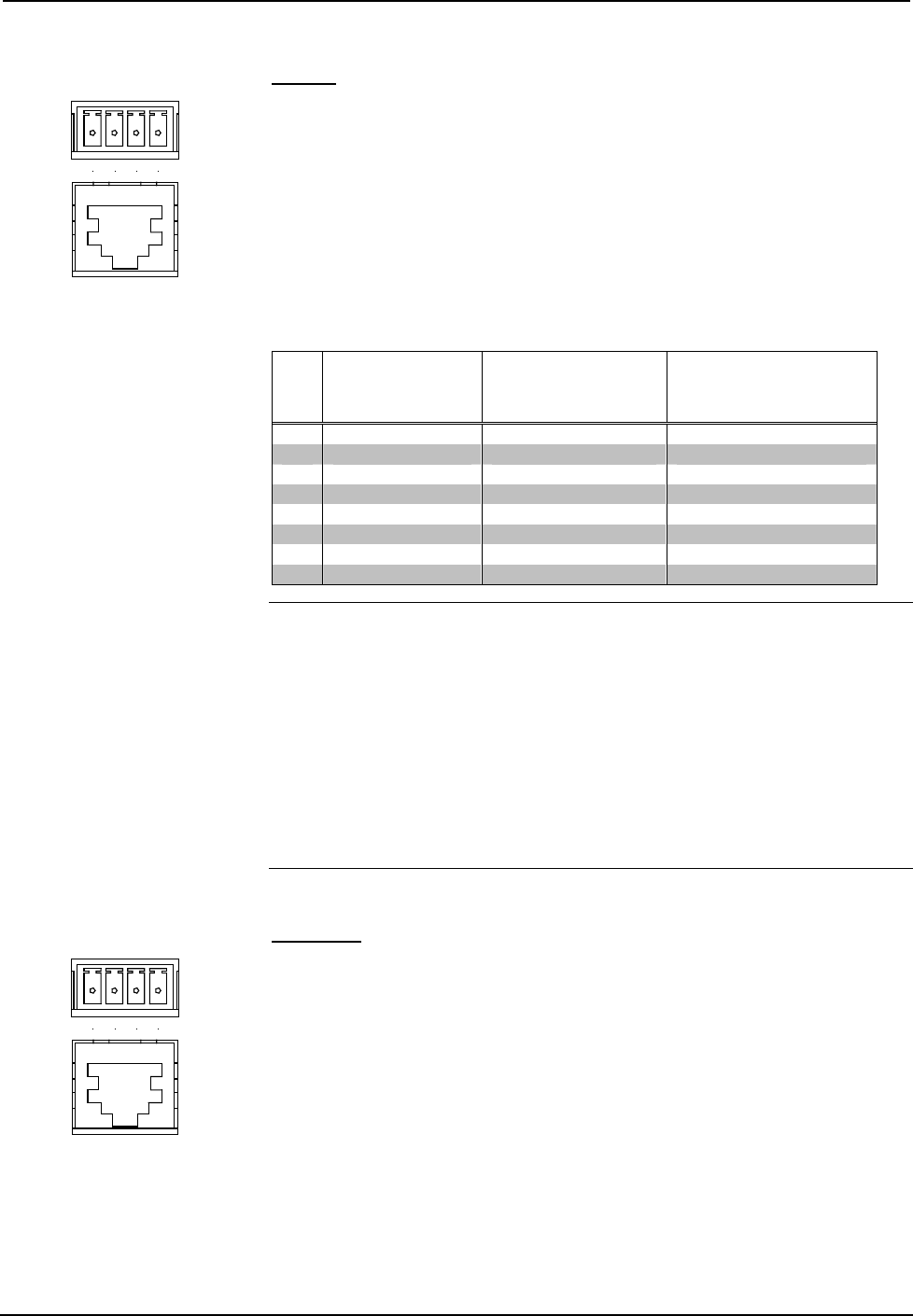
QM IN
G24 Y Z
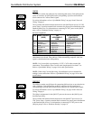
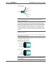
The MD4x2 contains four QM ports for connecting QM sources. Each QM port has
an RJ-45 connector for QM signals and a corresponding 4-position mini-terminal
block connector for Cresnet control signals.
For wiring information, refer to “QuickMedia Wiring” on page 10 and “Network
Wiring” on page 9.
The 4-position mini-terminal block connector on each QM IN port receives 24 VDC
power from a 2-position terminal block connector for proper power distribution to the
attached QM devices. For information on connecting 24 VDC power to the QM IN
ports, refer to “Hardware Hookup” on page 16.
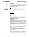
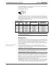
RJ-45 Pin Assignments
PIN WIRE COLORS
(568B)
QM
ASSIGNMENT:
RGB
QM ASSIGNMENT:
COMPOSITE,
S-VIDEO AND AUDIO
1 WHITE/ORANGE - RGB Red - CHROMINANCE
2 ORANGE + RGB Red + CHROMINANCE
3 WHITE/GREEN - RGB Green - LUMINANCE
4 BLUE + Digital Audio + AUDIO
5 WHITE/BLUE - Digital Audio - AUDIO
6 GREEN + RGB Green + LUMINANCE
7 WHITE/BROWN - RGB Blue - COMPOSITE
8 BROWN + RGB Blue + COMPOSITE
NOTE: When transmitting S-video, luminance uses the green video pathway, and
chrominance uses the red video pathway. When transmitting composite video, the
signal is carried on the blue video pathway.
NOTE: Use Crescat-QM, or good quality CAT5E / CAT6 cable to make QM
connections. The cumulative skew over the entire length must be less than 15 ns.
Refer to “QuickMedia Wiring” on page 10 for cable specifications.
NOTE: When using Crescat-QM wiring, four additional wires are included for
making Cresnet connections. Refer to “QuickMedia Wiring” on page 10 for cable
specifications.
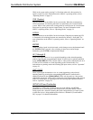
QM OUT
G24 Y Z
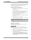
The MD4x2 contains two QM ports for connecting QM receivers or any other device
with a QM input. Each QM port has an RJ-45 connector for QM signals and a
corresponding 4-position mini-terminal block connector for Cresnet control signals.
For wiring information, refer to “QuickMedia Wiring” on page 10 and “Network
Wiring” on page 9.
The QM pin assignments for the QM OUT ports are the same as the QM IN ports
described previously.
The 4-position mini-terminal block connector on each QM OUT port receives 24
VDC power from a 2-position terminal block connector for proper power distribution
to the attached QM devices. For information on connecting 24 VDC power to the
QM port groups, refer to “Hardware Hookup” on page 16.
6 • QuickMedia Distribution System: QM-MD4x2 Operations Guide - DOC. 6278


Find Your Products By Category
- Computer Equipment
- Portable Media
- Photography
- Car Audio and Video
- TV and Video
- Household Appliance
- Automotive
- Communications
- Kitchen Appliance
- Laundry Appliance
- Home Audio
- Lawn and Garden
- Power Tools
- Musical Instruments & Equipment
- Baby
- Personal Care
- Video Game
- Marine Equipment
- Fitness & Sports
- Outdoor Cooking
- Cell Phone
Please Login
