

0
Owner's of the Humminbird Fish Finder 409010-1 gave it a score of 0 out of 5. Here's how the scores stacked up:
11
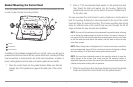
Installation - Power
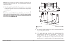
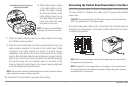
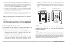
10. While holding cables in place
in the cable collector insert,
thread the cables through
the slot in the bottom of the
cable collector cover, line up
the cable collector insert and
cover, then slide the cover
into place on the insert.
NOTE: The tab on the Cable Collector
insert goes into the slot on the cover.
11. Attach the cable collector insert to the cable collector cover using
the 2 Phillips screws provided.
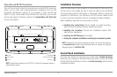
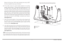
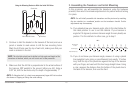
12. Place the control head back onto the mounting bracket. Plug in the
cable collector assembly to the back of the control head. Cable
connectors and cable sockets are keyed to prevent reverse
installation, so be careful not to force the connectors into the wrong
sockets. Once the cable collector and all cables are plugged into the
back of the control head, lock the assembly into place by threading
the knurled screw into the threaded insert on the back of the
housing. Adjust the control head to the desired viewing angle and
secure by tightening the gimbal knobs.
NOTE: You may wish to dress the cabling with nylon wire ties in order to holdthe
cables together and create a cleaner assembly.
The Humminbird® control head is now ready for operation.
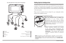
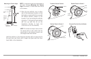
Connecting the Control Head Power Cable to the Boat
A 6' (2 m) long power cable is included to supply power to the control head.
You may shorten or lengthen the cable using 18 gauge multi-stranded
copper wire.
CAUTION: Some boats have 24 or 36 Volt electric systems, but the control head
MUST be connected to a 12 VDC power supply.
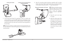
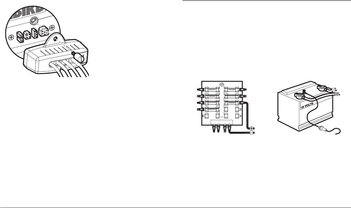
The control head power cable can be connected to the electrical system of
the boat at one of two places: a fuse panel usually located near the console,
or directly to the battery.
NOTE: Make sure that the power cable is disconnected from the control head at
the beginning of this procedure.
NOTE: Humminbird® is not responsible for over-voltage or over-current failures.
The control head must have adequate protection through the proper selection
and installation of a 3 amp fuse.
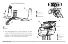
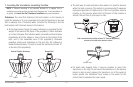
Plug Cable Connector Assembly to
Back of Control Head
GROUNDGROUND
POSITIVEPOSIT IVE


Find Your Products By Category
- Computer Equipment
- Portable Media
- Photography
- Car Audio and Video
- TV and Video
- Household Appliance
- Automotive
- Communications
- Kitchen Appliance
- Laundry Appliance
- Home Audio
- Lawn and Garden
- Power Tools
- Musical Instruments & Equipment
- Baby
- Personal Care
- Video Game
- Marine Equipment
- Fitness & Sports
- Outdoor Cooking
- Cell Phone
Please Login
