
0
Owner's of the Atlona Microscope & Magnifier Atlona HDBaseT Extender Family gave it a score of 0 out of 5. Here's how the scores stacked up:
4
ETHERNET
CAT5e/6/7 OUT
DC 24V
-
+
FIRMWARE
DVI IN
LINK
POWER
RS232
IR IN
AT-DVITX-RSNET
PWR
IR
RX TX
IR OUT
-
+
ETHERNET
CAT5e/6/7 IN
FIRMWARE
DVI OUT
LINK
POWER
RS232
IR IN
AT-DVIRX-RSNET
PWR
IR
RX TX
IR OUT
-
+
ETHERNET
CAT5e/6/7 OUT
DC 24V
-
+
FIRMWARE
DVI IN
LINK
POWER
RS232
IR IN
AT-DVITX-RSNET
PWR
IR
RX TX
IR OUT
-
+
ETHERNET
CAT5e/6/7 IN
FIRMWARE
DVI OUT
LINK
POWER
RS232
IR IN
AT-DVIRX-RSNET
PWR
IR
RX TX
IR OUT
-
+
atlona.com
Toll free: 1-877-536-3976
Local: 1-408-962-0515
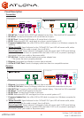
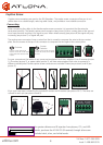
Panel Description
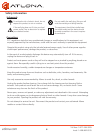
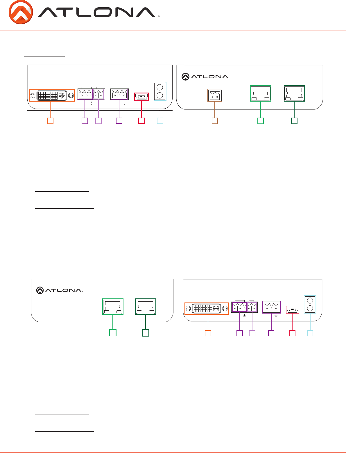
Transmitter
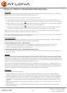
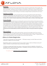
Receiver
1. DVI IN Port: Connect DVI or HDMI (with adapter) source here. *Not dual link DVI compatible*
2. IR IN Port: Connect an IR receiver or IR control box to this port.
3. IR OUT Port: Connect the IR Emitter or IR control box to this port.
4. RS232: Bidirectional RS-232, send signal to or from a control system or PC.
5. Firmware Update Port: Use a Mini USB to USB A cable to connect to a Windows computer for
updating.
6. Yellow Link LED: Signal Indicator for the CAT5e/6/7 OUT port. LED will remain solid, unless
there is an issue with the cable or signal, then it will blink.
Green Power LED: Power indicator. If plugged in light will remain solid. If LED starts blinking
power is intermittent or there is a problem with the cable. If LED is off, no power is passing to
the receiver (check your outlet or the power cable).
7. DC 24V Port: Connect included captive screw power adapter here.
**Be certain the wire is properly polarized
8. Ethernet: Send signal to a display or source from a network
9. CAT5e/6/7 OUT Port: Connect a category cable from here to a compatible receiver.
1. Ethernet: Send signal to a display or source from a network.
2. CAT5e/6/7 IN Port: Connect a category cable from a compatible transmitter to this port.
3. DVI OUT Port: Connect to DVI or HDMI (with adapter) display. *Not dual link DVI compatible*
4. IR IN Port: Connect the IR receiver to this port.
5. IR OUT Port: Connect the IR Emitter to this port.
6. RS232: Bidirectional RS-232 send signal to or from a control system or PC.
7. Firmware Update Port: Use a Mini USB to USB cable to connect to a Windows computer for
updating.
8. Yellow Link LED: Signal Indicator for the CAT5e/6/7 OUT port. LED will remain solid, unless
there is an issue with the cable or signal, then it will blink.
Green Power LED: Power indicator. If plugged in light will remain solid. If LED starts blinking
power is intermittent or there is a problem with the cable. If LED is off, no power is passing to
the receiver (check your outlet or the power cable).
2
1
5
4
7
6 7
6
98
8
2
4
1
3
3
5


Find Your Products By Category
- Computer Equipment
- Portable Media
- Photography
- Car Audio and Video
- TV and Video
- Household Appliance
- Automotive
- Communications
- Kitchen Appliance
- Laundry Appliance
- Home Audio
- Lawn and Garden
- Power Tools
- Musical Instruments & Equipment
- Baby
- Personal Care
- Video Game
- Marine Equipment
- Fitness & Sports
- Outdoor Cooking
- Cell Phone
Please Login
