
3.4
Owner's of the APC Remote Starter REMOTE POWER-OFF DEVICE gave it a score of 3.4 out of 5. Here's how the scores stacked up:
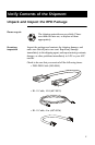
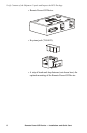
12 Remote Power-Off Device — Installation and Quick Start
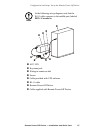
Configure the Remote Power-Off Device
Types of remote
switches
supported
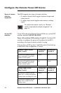
The RPO supports two types of remote switches:
• A contact closure switch toggles between an open and
closed circuit.
• A voltage input switch applies and removes a voltage
signal.
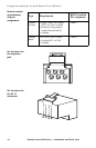
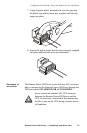
Set the DIP
switches
On the UPS side of the Remote Power-Off Device, set the DIP
switches labeled CONFIGURATION.
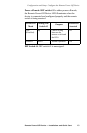
Power-off condition: DIP switches #1 and #2. Use these DIP
switches to configure the power-off condition for the RPO
according to the type of remote switch it is using.
If the positions of DIP switch #1 and DIP switch #2 are both up
or both down, the configuration is invalid.
To connect the remote switch, see “Remote
switch: requirements and pin assignment” on
page 16.
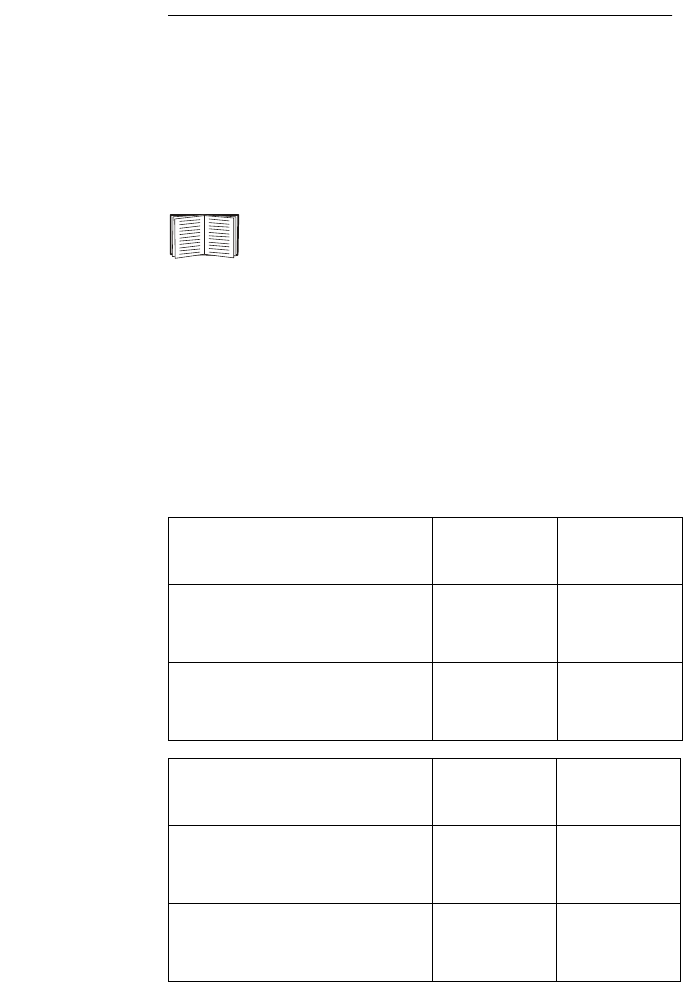
Contact Closure Switch
(Pins 2 and 5)
Setting: DIP
Switch #1
Setting: DIP
Switch #2
A power-off condition occurs
when a normally closed (NC)
contact closure opens.
down up
A power-off condition occurs
when a normally open (NO)
contact closure opens.
up down
Voltage Input Switch
(Pins 3 and 4)
Setting: DIP
Switch #1
Setting: DIP
Switch #2
A power-off condition occurs
when 24 V is removed from the
voltage input, resulting in 0 volts.
down up
A power-off condition occurs
when 24 V is applied to the
voltage input.
up down


Find Your Products By Category
- Computer Equipment
- Portable Media
- Photography
- Car Audio and Video
- TV and Video
- Household Appliance
- Automotive
- Communications
- Kitchen Appliance
- Laundry Appliance
- Home Audio
- Lawn and Garden
- Power Tools
- Musical Instruments & Equipment
- Baby
- Personal Care
- Video Game
- Marine Equipment
- Fitness & Sports
- Outdoor Cooking
- Cell Phone
Please Login
