
0
Owner's of the Axis Communications Security Camera 463001 gave it a score of 0 out of 5. Here's how the scores stacked up:

AXIS Q1604-E Network Camera
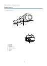
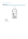
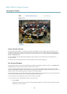
Hardware Overview
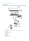
15.
Bracket screws (4x)
16.
Bracket adapter
17.
Network cable (route through wall bracket). Cable not included
18.
Wall bracket
19.
Bracket adjustment screw
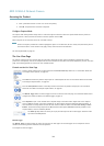
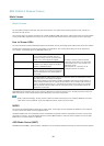
Cold Startup Delay Switch
The Cold Startup Delay switch, when turned on, controls how the camera restarts after a power cut, when temperatures are below
0 °C (32 °F). The camera is rst heated to approximately 0 °C (32 °F) before it initializes. This prevents damage to camera parts
sensitive to sub-zero temperatures.
Connectors and Buttons
For technical specications, see page 60.
Network Connector
RJ45 Ethernet connector. Supports Power over Ethernet (PoE).
NOTICENOTICE
NOTICE
The product shall be connected using a shielded network cable (STP). All cables connecting the product to the network switch
shall be shielded (STP) and intended for their specic use. Make sure that the network switch is properly grounded. For
information about regulatory requirements, see Regulatory Information, on page 2 .
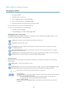
I/O Connector
Use with external devices in combination with, for example, tampering alarms, motion detection, event triggering, time lapse recording
and alarm notications. In addition to the 0 V DC reference point and power (DC output), the I/O connector provides the interface to:
• Digital output – For connecting external devices such as relays and LEDs. Connected devices can be activated by the
VAPIX® Application Programming Interface, output buttons on the Live View page or by an Action Rule. The output will
show as active (shown under System Options > Ports & Devices) if the alarm device is activated.
• Digital input – An alarm input for connecting devices that can toggle between an open and closed circuit, for example:
PIRs, door/window contacts, glass break detectors, etc. When a signal is received the state changes and the input becomes
active (shown under System Options > Ports & Devices).
Note
The I/O connector is connected to the housing (fan/heater) on delivery. In the case of a fan or heater error, an input signal
will be triggered in the camera. Set up an action rule in the camera to congure which action the signal shall trigger. For
information about events and action rules, see Events, on page 37.
Power Connector
2-pin terminal block for power input. Use a Safety Extra Low Voltage (SELV) compliant limited power source (LPS) with either a rated
output power limited to ≤100 W or a rated output current limited to ≤5 A.
Audio Connector
The Axis product has the following audio connectors:
• Audio in (pink) – 3.5 mm input for a mono microphone, or a line-in mono signal (left channel is used from a stereo signal).
• Audio out (green) – 3.5 mm output for audio (line level) that can be connected to a public address (PA) system or an
active speaker with a built-in amplier. A stereo connector must be used for audio out.
9


Find Your Products By Category
- Computer Equipment
- Portable Media
- Photography
- Car Audio and Video
- TV and Video
- Household Appliance
- Automotive
- Communications
- Kitchen Appliance
- Laundry Appliance
- Home Audio
- Lawn and Garden
- Power Tools
- Musical Instruments & Equipment
- Baby
- Personal Care
- Video Game
- Marine Equipment
- Fitness & Sports
- Outdoor Cooking
- Cell Phone
Please Login
